Display solutions for iMX based COM boards
Available Display Interfaces
The i.MX 6/7/8 application processor families are very versatile:
- Up to 5 different display interfaces available
- 2-4 interfaces can be active simultaneously
- All display interface signals are available on the EACOM board edge connector
| EACOM board | Parallel RGB | LVDS#0 | LVDS#1 | HDMI | MIPI-DSI |
|---|---|---|---|---|---|
| iMX6 UltraLite | ✔ | ||||
| iMX6 SoloX | ✔ | ✔ | |||
| iMX6 DualLite | ✔ | ✔ | ✔ | ✔ | ✔ |
| iMX6 Quad | ✔ | ✔ | ✔ | ✔ | ✔ |
| iMX7 Dual | ✔ | ✔ | |||
| iMX7 Dual uCOM | ✔ | ✔ | |||
| iMX7ULP uCOM | ✔1 | ✔ | |||
| iMX8M COM | ✔ | ✔ | |||
| iMX8M Mini uCOM | ✔1 | ✔ |
1 Via MIPI-DSI to HDMI bridge on the uCOM Adapter board
The table above illustrates which display interfaces are available on different EACOM boards.
Some characteristics of the different display interfaces:
- Parallel RGB
This interface is common for smaller, internal displays with horizontal resolution up to about 800 pixels (up to about 7 inch displays). Up to 24-bit color depth is supported. - LVDS
This interface is common for larger, internal displays.
For 18-bit color depth, one clock and three data lanes are used. For 24-bit color depth, one more data lane is added. - HDMI/DVI
This interface is common for larger, external displays/monitors. Both HDMI and DVI-I uses the same underlying signaling technology, TMDS, which is a differential signaling serial bus. - MIPI-DSI
This interface is common on small, high-resolution displays for handheld equipment, like mobile phones and tablets.
It is a differential signaling serial bus with one clock lane and one or more data lanes (1-2 data lanes supported).
Because of EMC, a parallel RGB interface should only be used over short distances with well-controlled trace impedance and low pixel clock frequency (<20MHz). If length or clock frequency increase, a differential signaling bus should be considered.
For more details about available display interfaces and how to add displays,
read our document Adding Displays to iMX Developer’s Kits.
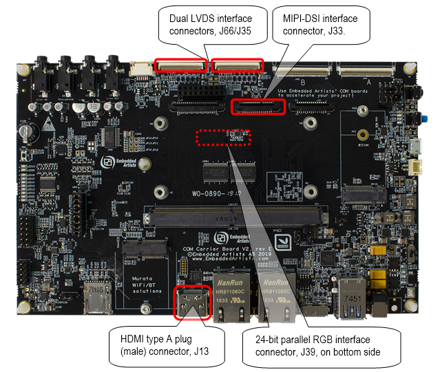
COM Carrier board V2
Our iMX Developer’s Kits V2 builds upon the COM Carrier Board V2. iMX Developer’s Kits are typically used in the proof-of-concept and prototype phase of a project. Hence, the task of “adding a display” will typically be the same as interfacing it to the COM Carrier Board V2. The picture to the right illustrates the location of the display interface connectors.

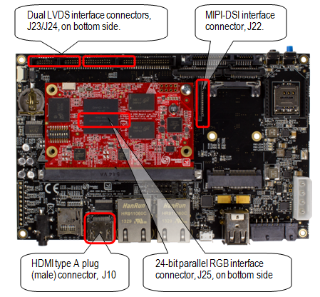
COM Carrier board
Our iMX Developer’s Kits builds upon the COM Carrier Board. iMX Developer’s Kits are typically used in the proof-of-concept and prototype phase of a project. Hence, the task of “adding a display” will typically be the same as interfacing it to the COM Carrier Board. The picture to the right illustrates the location of the display interface connectors.

COM Display Adapter – For Parallel RGB
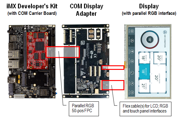
The COM Display Adapter is a reference design for the small adapter board that is needed when connecting any parallel RGB display. The board contains:
- adjustable current backlight driver (20-160mA)
- resistive touch panel controller, AR1021 from Microchip
- connectors to different capacitive touch panel controllers to supported displays (with I2C interfaces)
The picture below illustrates how the COM Display Adapter is connected to the COM Carrier Board and an LCD.

Below is a list of (some) supported displays
Many, but not all, of the listed display have been verified to work. Some have been verified to be compatible via their respective datasheets.
| Display size (inch) | Resolution | Touch panel | Manufacturer | Part number |
|---|---|---|---|---|
| 4.3 | 480 x 272 | Resistive | Rogin | RX043A-0207-T |
| 4.3 | 480 x 272 | – | NewHaven | NHD-4.3-480272EF-ATXL# |
| 4.3 | 480 x 272 | Resistive | NewHaven | NHD-4.3-480272EF-ATXL#-T |
| 4.3 | 480 x 272 | Capacitive | NewHaven | NHD-4.3-480272EF-ATXL#-CTP |
| 4.3 | 480 x 272 | – | NewHaven | NHD-4.3-480272EF-ASXN# |
| 4.3 | 480 x 272 | Resistive | NewHaven | NHD-4.3-480272EF-ASXN#-T |
| 4.3 | 480 x 272 | Capacitive | NewHaven | NHD-4.3-480272EF-ASXN#-CTP |
| 4.3 | 480 x 272 | – | NewHaven | NHD-4.3-480272EF-ASXV# |
| 4.3 | 480 x 272 | Resistive | NewHaven | NHD-4.3-480272EF-ASXV#-T |
| 4.3 | 480 x 272 | Capacitive | NewHaven | NHD-4.3-480272EF-ASXV#-CTP |
| 4.3 | 480 x 272 | – | EDT | ET043080DM6 |
| 4.3 | 480 x 272 | Resistive | EDT | ET043080DH6 |
| 4.3 | 480 x 272 | Capacitive | URT | UMSH-8864MD-10T |
| 5.0 | 800 x 480 | Resistive | Rogin | RX050A-05-T |
| 5.0 | 800 x 480 | Capacitive | URT | UMSH-8837MD-4T |
| 5.0 | 800 x 480 | – | NewHaven | NHD-5.0-800480TF-ATXL# |
| 5.0 | 800 x 480 | Resistive | NewHaven | NHD-5.0-800480TF-ATXL#-T |
| 5.0 | 800 x 480 | Capacitive | NewHaven | NHD-5.0-800480TF-ATXL#-CTP |
| 5.0 | 800 x 480 | – | EDT | ET050080DM6 |
| 5.0 | 800 x 480 | Resistive | EDT | ET050080DH6 |
| 7.0 | 800 x 480 | – | NewHaven | NHD-7.0-800480EF-ATXL# |
| 7.0 | 800 x 480 | Resistive | NewHaven | NHD-7.0-800480EF-ATXL#-T |
| 7.0 | 800 x 480 | Capacitive | NewHaven | NHD-7.0-800480EF-ATXL#-CTP |
| 7.0 | 800 x 480 | – | NewHaven | NHD-7.0-800480EF-ATXV# |
| 7.0 | 800 x 480 | Resistive | NewHaven | NHD-7.0-800480EF-ATXV#-T |
| 7.0 | 800 x 480 | Capacitive | NewHaven | NHD-7.0-800480EF-ATXV#-CTP |
| 7.0 | 800 x 480 | – | EDT | ET070080DM6 |
| 7.0 | 800 x 480 | Resistive | EDT | ET070080DH6 |
| 7.0 | 800 x 480 | Resistive | Innolux | AT070TN83 |
| 7.0 | 800 x 480 | Capacitive | URT | UMSH-8596MD-30T |
If a specific display is not supported by the COM Display Adapter, then it can be used as a reference to create an adapter board that fits the specific display perfectly.
For more details about the COM Display Adapter, see the product page for the board.
Custom adapter cable – For displays with LVDS interface
The two LVDS interfaces on the COM Carrier Board V1 connect directly to NXP’s 10.1 inch (1024 x 768 pixels) LVDS reference display (MCIMX-LVDS1). For the COM Carrier Board V2 the LVDS interfaces connect directly to a New Haven 10.1 inch display (NHD-10.1-1024600AF-LSXV-CTP) .This is a very quick way to get an LVDS display up-and-running… just plug it in!
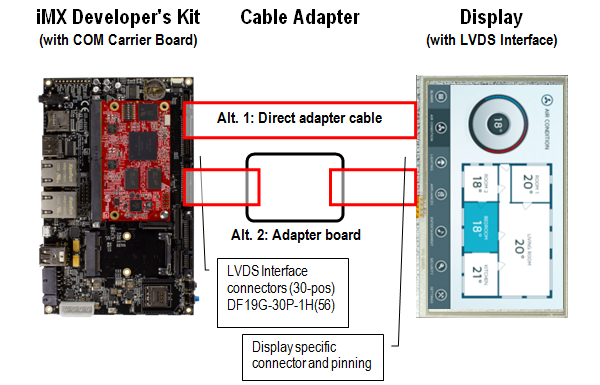
For other displays with LVDS interface an adapter cable, or small adapter board, must be designed. There is no standard adapter cable or board available since there are many different connectors and different pinnings involved. It has to be created on a case-by-case basis, but fortunately this task is typically very simple. The picture below illustrates the two options:
- If the display’s LVDS interface is similar to the COM Carrier Board LVDS connector, a simple adapter cable can typically be created.
- If the display’s LVDS interface has significant differences to the COM Carrier Board LVDS connector, a small adapter board will have to be created. It can for example contain connector adaptations and backlight driving.

