LOADING
- Small size: 21 x 40 mm
- Drag-and-drop programming
- SWD/JTAG connector

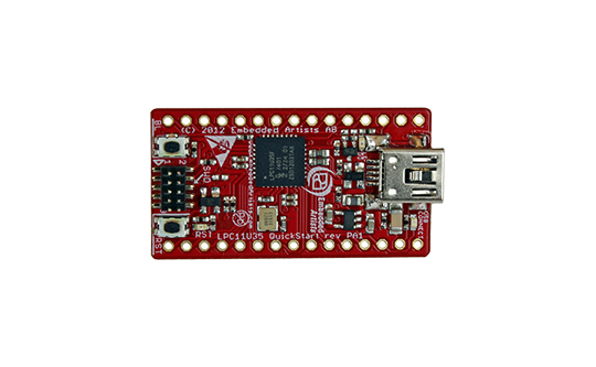
The LPC11U35 QuickStart Board lets you get up-and-running quickly with NXP's Cortex-M0 LPC11U35 microcontroller
Easy usage
Download code to the board by using:
- The USB-ISP mode where the board will enumerate as a USB Mass storage device on a Windows PC. Just copy the compiled binary file to the storage device.
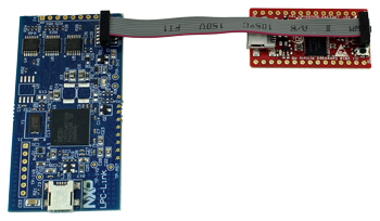
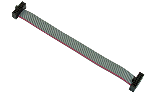
- Use the free LPCXpresso IDE/Debugger together with, for example, an LPC-Link, a 10-pos IDC Ribbon cable and connect to the SWD interface (10-pin JTAG connector) on the board, see figure below. This allows you to both download and debug code on the board.
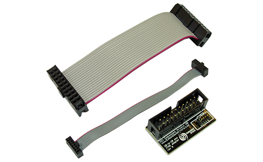
- Use a debugger and JTAG adapter of your choice which supports the Cortex-M3 ARM core and more specifically the NXP LPC11U35 microcontroller. You might need an adapter such as the 10-pin to 20-pin JTAG Adapter Kit between your JTAG solution and the target board.

| Processor | |
|---|---|
| NXP's Cortex-M0 LPC11U35 microcontroller in 33-pin HVQFN package. | |
| 64 KByte flash. | |
| 10 KByte RAM. | |
| 4 KByte EEPROM | |
| Interfaces / Connectors | |
|---|---|
| All LPC11U35 I/O pins are available on edge expansion connectors, in DIL-30 structure suitable for bread board prototyping (dual 15 pos, 100 mil/2.54 mm pitch rows, 700 mil/17.78 mm apart). | |
| On-board USB Device interface, with mini-B USB connector and proper ESD protection. | |
| SWD/JTAG connector (50 mil/1.27 mm pitch, standard SWD/JTAG connector). | |
| Power | |
|---|---|
| Flexible powering, with on-board 150mA 3.3V voltage regulator (can be powered from USB connector or an external +5V supply). | |
| Other | |
|---|---|
| Onboard reset generation and reset push-button. | |
| Push-button for enabling Bootloader mode of the LPC1343. | |
| LED on pin PIO0_7. | |
| 2 pcs 1x15 pinlists included, but not soldered. | |
| Dimensions: 21 x 40 mm | |
| Flyers and specifications | |
|---|---|
| LPC11U35 QSB schematics | |
| LPC11U35_QuickStart_Board.lbr | |
| Documentation and guides | |
|---|---|
| LPC11U35 QuickStart Board User's Guide | |


